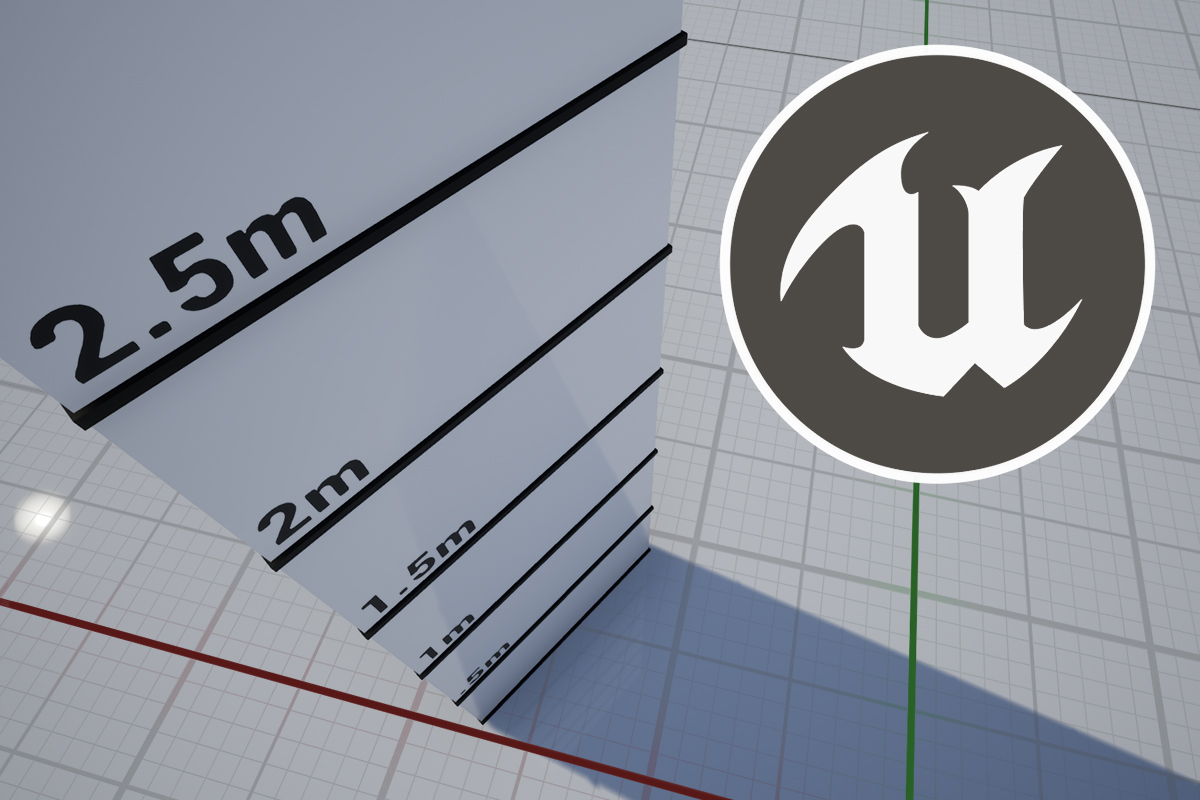
I don’t think I am exaggerating too much when I say that a versatile grid shader is at the core of a level designer’s toolkit. While blocking out a new scene the grid provides a proper sense of both scale and distance, and helps delineate between surfaces. If the grid also makes your blockout look a little prettier, then that’s even better!
In this tutorial we’ll be using Unity’s Shader Graph to create a multipurpose world-space grid for both the Universal and High Definition Render Pipelines. With a range of features and being entirely procedural, the shader will be highly customizable and look good at any scale.
Download the Unity project
You can download both the URP and HDRP versions of the shader (they’re virtually identical) from the project’s GitHub repository. Feel free to use them in your own projects however you like!If you’re an Unreal Engine developer you might also be pleased to know that I have created an Unreal version of this shader which you can download here.
In the following sections we’ll be going through the shader creation process step-by-step. If you’re already confident you know your way around Shader Graph and you just want to see my implementation, here is what my graph looks like in version 2021.2.6f1.

Working with the shader
Before we jump into the creation process, I think it’s best to give you a brief rundown of how the finished shader works so you can decide for yourself which features are worth including.
Quick note
As we’ve already covered here on techarthub, Unity units are usually measured in meters. Inside our shader I am dividing certain parameters by 100 because I prefer to work in centimeters.

Grid
- Line color
The color of the shader’s grid lines. White (1,1,1) by default. - Primary grid size
The length of a single grid cell in centimeters. By default this is set to 50, which means grid lines will be spaced at half-meter intervals. - Primary grid line width
The thickness of the primary grid lines. The strength of the two lines that intersect the origin will be double this setting. I found a value of 0.02 looks best in my demo scene. - Use secondary grid
This boolean will toggle an additional set of grid lines. By default this is set to true, because subdivisions are sexy. - Secondary grid size
The size of the secondary grid’s cells, in centimeters. I have set this to 25 by default to create a 4×4 grid within each primary grid cell. - Secondary grid line width
Set to 0.005 by default, a quarter of the primary grid’s line width. - Secondary grid intensity
This parameter lets you set the intensity of the secondary grid lines, to help with visual clarity. A value of 1.0 makes the secondary grid as visible as the primary grid, and a value of 0 will fade it out completely. - Secondary grid fade length
To avoid the grid lines appearing to crowd each other when viewed at longer distances, the shader will start to fade the secondary grid out as the camera moves further from its surface.
This setting is the distance from the surface to the camera at which the secondary grid will be completely faded out. By default it’s set to 8 meters, but you’ll need to tweak this setting depending on the fineness of your secondary grid lines. - Secondary grid fade offset
Use this setting to offset the distance at which your secondary grid starts to fade.

Checker
- Wall color
The color of the shader when applied to vertical surfaces. - Floor color
The color of the shader when applied to horizontal surfaces. - Checker size
The size in centimeters of one iteration of the checker pattern. I tend to keep this setting either the same or double the size of the primary grid. - Checker contrast
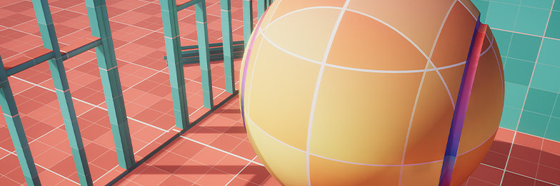
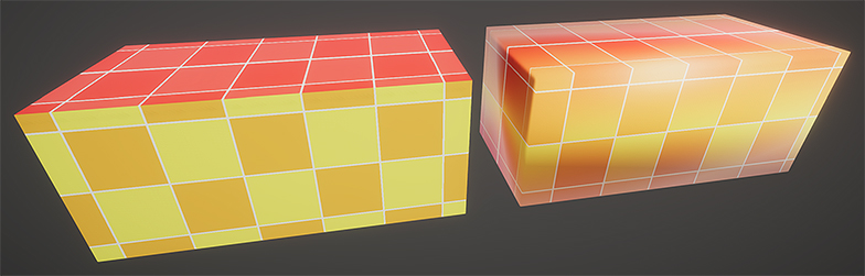
This will control the contrast of the checker pattern, with a value of 1 showing no visible pattern. Increasing/decreasing this value will change the pattern’s contrast in different ways. - Project transition contrast
This value will dictate how much the material should blend colors between horizontal and vertical surfaces. The higher value, the harsher the transition. By default I have set this to 0 which means on sloped surfaces the colors will be evenly blended together.
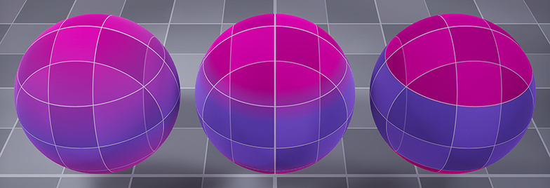
In this example I’m using values (from left to right) of 0, 1, and 32.
Building the shader
To get started you’ll need to create a few new assets in a project using the render pipeline of your choice. The process is very similar whether you’re using the URP or HDRP (or even other node-based shader editors, like Amplify)
You’re going to need the following:
- A Shader Graph called S_ProceduralGrid
URP: Shader/Universal Render Pipeline/Lit Shader Graph
HDRP: Shader/HD Render Pipeline/Lit Shader Graph - Two shader Sub Graphs called SG_GridLines and SG_Checker respectively.
- A Material called M_ProceduralGrid from which you can assign your new shader.

If you’ve never used Sub Graphs before, don’t worry. Think of them as reusable functions that you can call from within your shader so you can reduce the amount of clutter in your graph. They’re super useful, and make what we’re doing here much more easily extended. If you want more of a rundown on Sub Graphs check out this video created by Wilmer Lin.
SG_GridLines
We’ll start with the creation of our Sub Graphs before we pull it all together. This first one is the simplest of the two and responsible for drawing a series of arbitrarily spaced world space grid lines.
It’s not large, but it does some important math for us. The section highlighted in red generates our grid in three dimensions by dividing the world position of each pixel by our grid size input. It then multiplies the remainder by itself, which gets us something that looks like this.

This gets us almost all of the way there, but there is one small problem. At specific world space positions where a mesh’s face is lying parallel to a grid line, we get some very strange behaviour. This is because Unity is trying to draw multiple things on top of each other, and doesn’t know which one has priority.

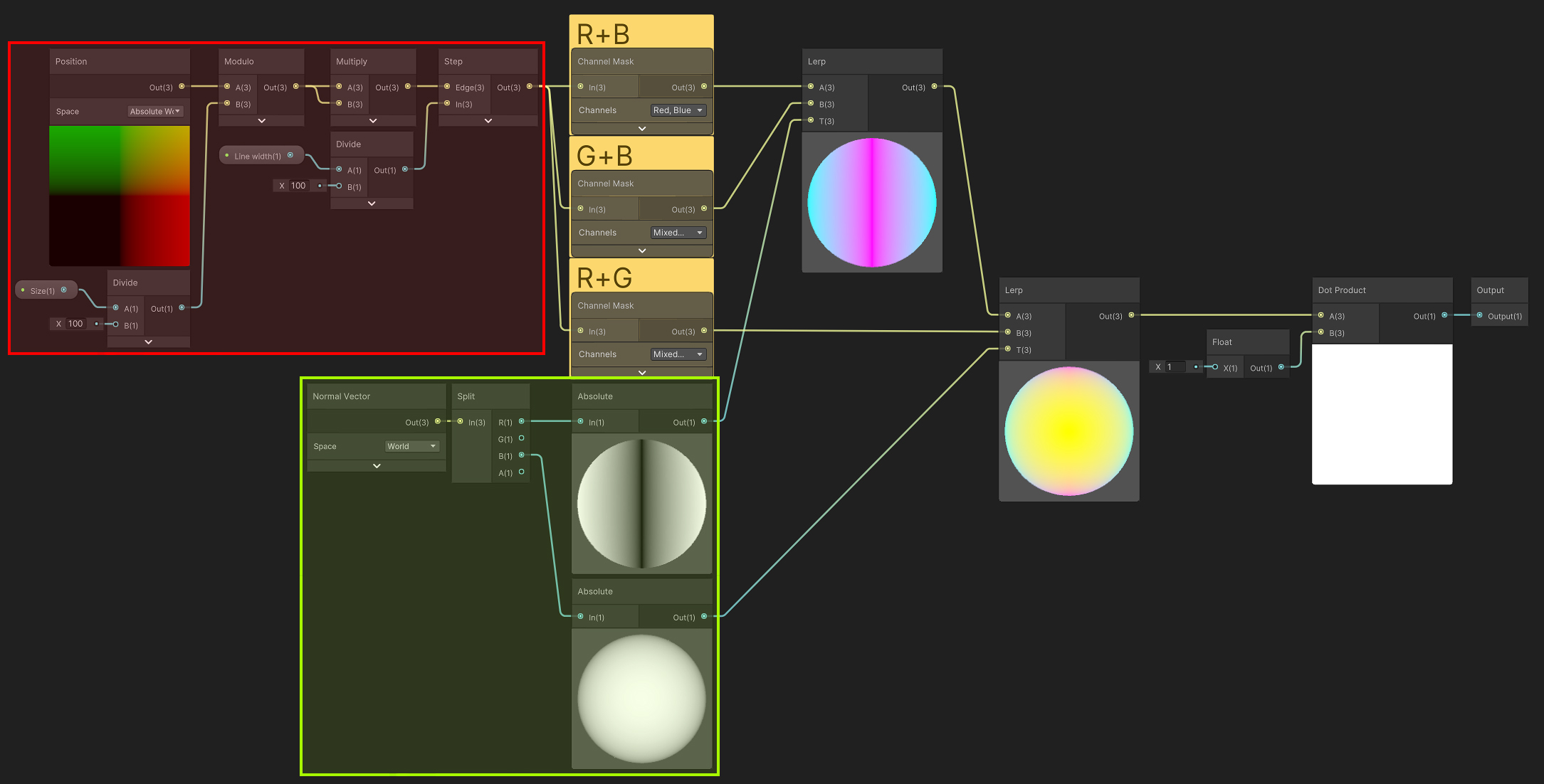
To solve this we have to be more explicit about what we want, which is what the rest of the Sub Graph does. Using two masks based on the vertex normal (highlighted in green), we blend three separate projections (R+B, G+B, and R+G) together to get the result we need.
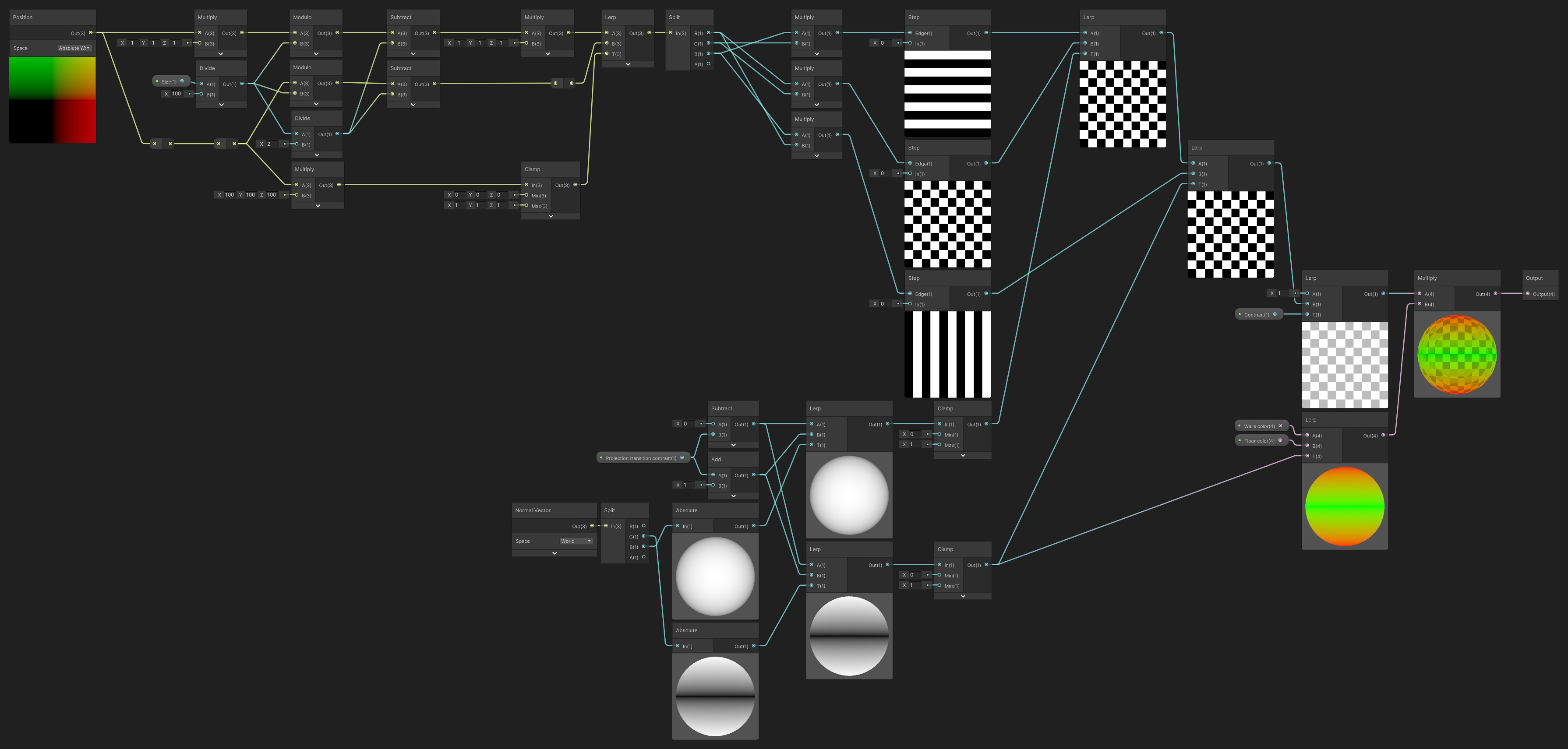
SG_Checker
The second Sub Graph is a little more technical, but follows the same basic principles.

We start off by once again dividing our arbitrary grid size and grabbing the remainder, but in this instance we’re also dividing our grid size by 2 and subtracting the result from that remainder to generate our checker pattern.
The rest of the graph is a variant of our previous Sub Graph, where we split out three different projections, one each for X, Y, and Z, and then recombine them using our mesh’s vertex normal information.
We are also now modifying those vertex normal masks by a Projection transition contrast value.
Finally, we add some color and contrast control to our checker pattern’s output.

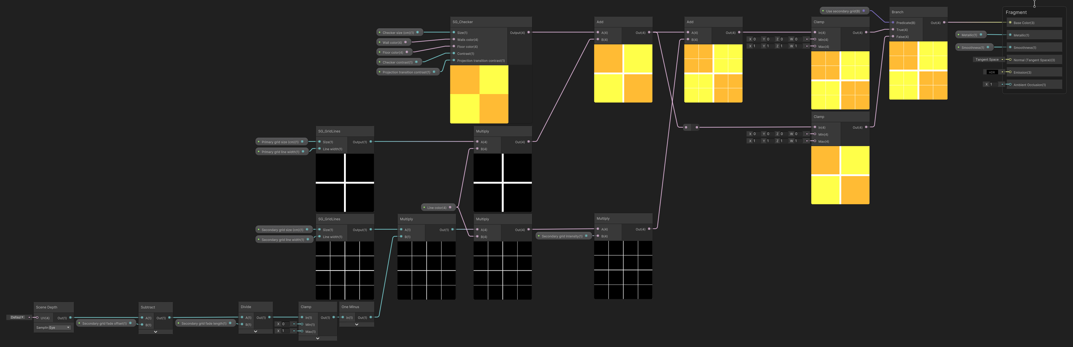
Bringing it all together
Now we’ve got all our components, it’s time to drop them into our S_ProceduralGrid graph. Luckily, the heavy lifting has now all been done.

This graph has three sections to it. Highlighted in red we have the primary grid, which calls the SG_GridLines Sub Graph and feeds some parameters into it.
We then feed the output of that section into the output of another SG_GridLines graph (green), which has some additional logic for fading the lines in and out based on the camera’s distance from the surface. This will make up our secondary grid.
Finally we drop a SG_Checker node into the graph, hook up some variables, and lerp the colors together.

Performance considerations
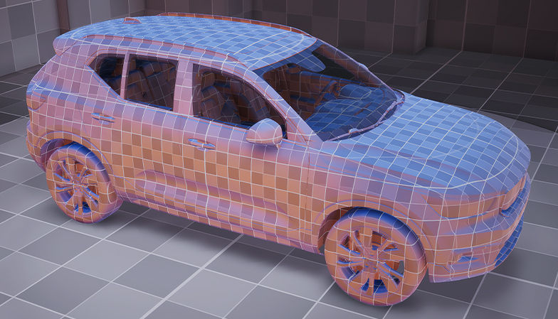
This procedural grid shader should work at any scale and with any mesh, static or skeletal. It uses very few texture samplers, and will prove to be a flexible and efficient tool to help you with your level blockouts.
If you’d like to make the shader even more performant you might consider using an unlit shader graph as your base instead. This will significantly reduce its complexity.
Thanks for reading, I hope you’ve found this tutorial useful. I’m keen to create more like this in the near future, so if you have any requests, comments, or questions please reach out.
Frequently Asked Questions
Is it possible to move or rotate the grid in object space instead?
Absolutely! If you want to rotate and/or move your grid in object space you’ll need to add a few small modifications to your Sub Graphs.
For both SG_GridLines and SG_Checker, change the settings of the starting Position from Absolute World to Object. If you’d also like the grid to keep its spacing with the rest of the world make sure you multiply those coordinates by the object’s scale.

How can I fix the weird results I get with smoothed vertex normals?
If you’re using smoothed vertex normals you may notice some flickering or strange blending in the checker pattern as it tries to interpret the direction of the grid.
One easy fix for this is to generate our own vertex normals. You can do this by adding a few additional nodes to the blending section of your SG_Checker Sub Graph. In this example I am also using a boolean parameter to switch between the mesh’s default vertex normal information and a set of generated hard-edged ones.